Case study
PCB Design Tips to Improve Yield During the Pick and Place Process
PCB Design Tips to Improve Yield During the Pick and Place Process
For those unfamiliar, Surface Mount Technology (SMT) component placement systems, or as we refer to them pick-and-place machines, are highly automated, robotic machines used to pick up surface mount components from tape, trays or tubes and place them onto printed circuit boards. Although using this process has exponentially increased the speed at which circuit boards can be assembled since the days of pure hand assembly, the process can go a lot slower or faster depending on how well the circuit board was designed by the engineer.
Here's our design suggestions for what you can do to make the pick and place go smoother for your CM, which will in turn improve yields and potentially also lower lead times and cost.
Choose larger size SMT parts whenever possible

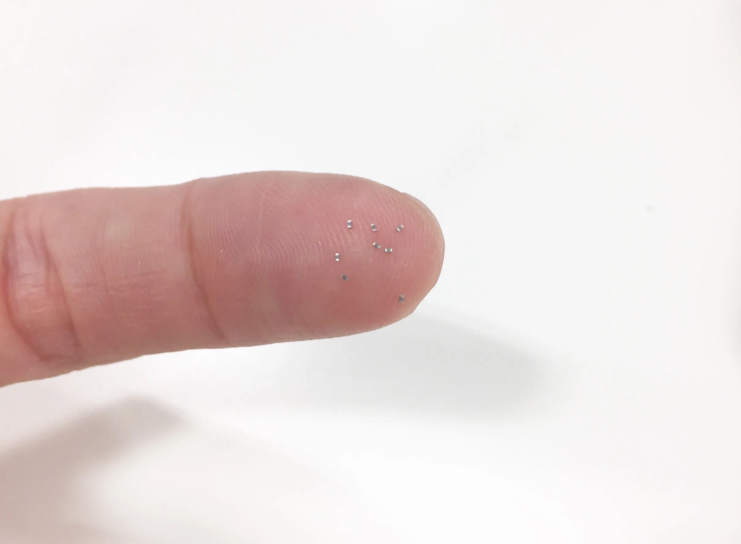
Choosing a 0402 package size or larger will make your CM happy (but go up to 0603 if you can).
Imagine you're an archer trying to hit a target. The larger the target the higher chance you're going to hit the bullseye every time. The smaller the target the more factors you have to consider in order to hit it.
In this case the pick and place vacuum nozzle head is the archer, the component is the arrow, and the footprint with wet solder applied is the target. The larger the component, the easier it becomes for the pick and place's internal vision system to accurately pick up the component and place it onto its footprint.
Keep in mind that we place 0201 components on a daily basis, so if you need to use them in your design we will have no issues. However, the increased attention they require to be placed accurately will be reflected in yields, lead times, etc.
Place enough space between parts

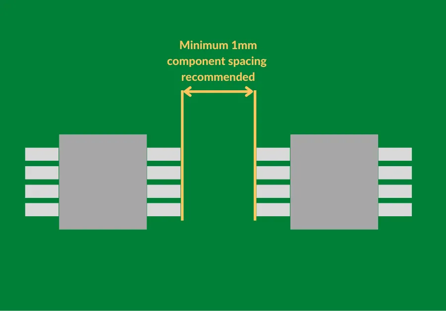
When designing your board, be mindful of how close together you are placing components. Our cozy recommendation is to leave one millimeter between parts if possible.
Placing parts too close together will require more setup time to determine the best order to place parts onto the board. For example, if there is a tall aluminum capacitor right next to a small 0402 resistor, you'll have to make sure to place the resistor first otherwise you risk the pick and place vacuum head colliding with the aluminum capacitor.
On very small boards leaving one millimeter between parts might not be realistic, but space out your components if you can.
Choose flat no lead components

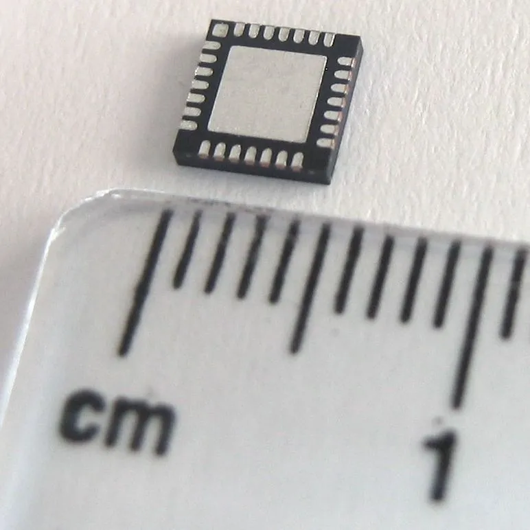
This may seem counterintuitive, but we recommend using flat, no lead components such as QFNs, DFNs or BGAs over components with leads.
Components with leads are fragile and can easily become damaged. No lead components are more difficult to damage and therefore tend to have better yields. Although BGA and QFN components are more difficult and expensive to rework, we have found less rework to be necessary in the first place.
Consider component height

Different models of pick and place machines have different limits on the height of components they can handle due to how high the head can move to get out of the way and also physical limitations such as safety glass. The average limitation is around 15-25mm. If you need a ton of capacitance consider using multiple smaller ones capacitors placed in parallel rather than using one really big tall one. This will ensure that that they do not need to be hand placed onto the PCB after reflow.
Avoid using a micro USB port in your design

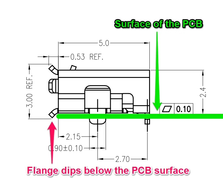
Considering the prevalence of micro USB ports we know this sounds a bit crazy, but we argue that they were not designed well for manufacturing. Micro USB ports have a flange that dips below the surface of the PCB in order to make it easier to plug in a cable. This flange sticks out below the surface of the PCB we require special accommodations when deciding how to panelize the board. Additionally, the holes on top of the micro USB port make it difficult for the pick and place vacuum head to pick up the part and also make it difficult for the vision system to pick up on all the fine details of the part, increasing the difficulty of accurately aligning it.
Instead, we recommend using a USB-C port. Even though they are more expensive and require more design considerations, we've found them easier to assemble and to have higher yields. Worthington Assembly has a great article on recommended USB-C ports.
If you're interested in learning more about the SMT pick and place process make sure to check out our podcast episode on the subject!


